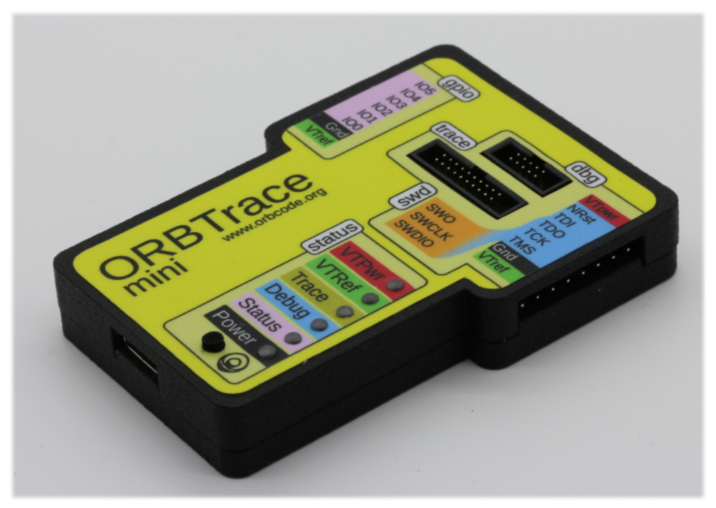
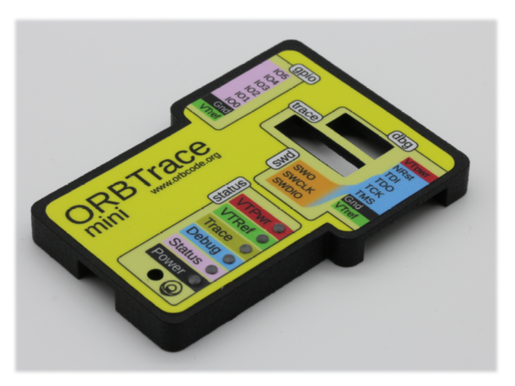
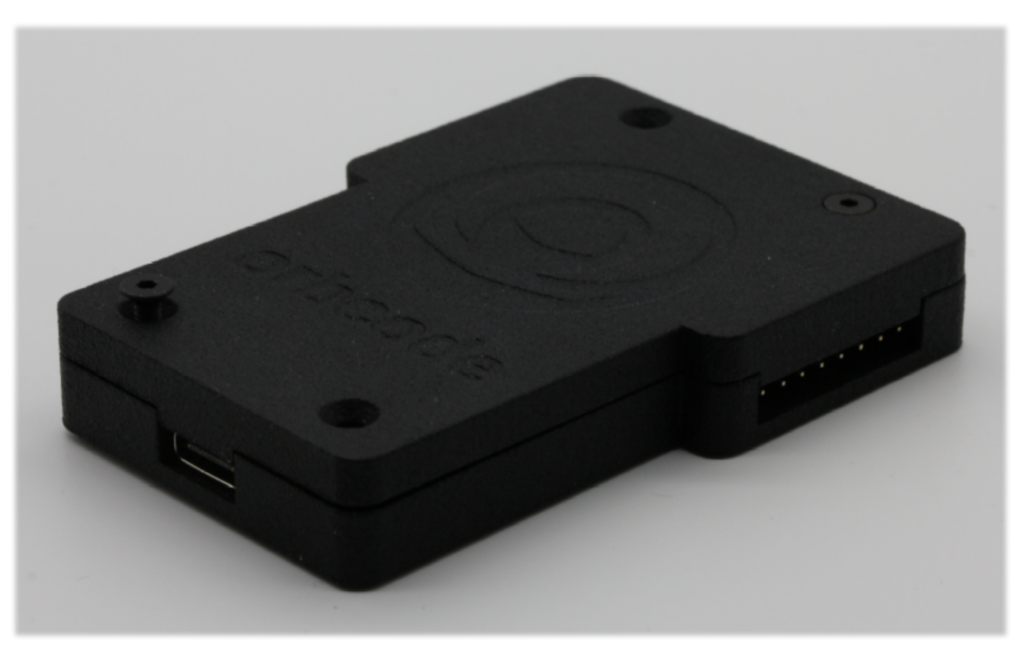
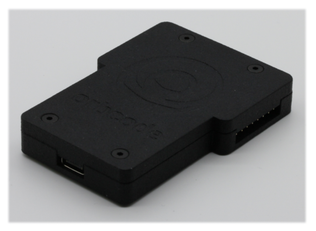
So, you finally got your ORBTrace Mini, and to keep it in pristine condition you got the case too. Wouldn’t it be nice if someone had written an illustrated guide on how to assemble it all?
0. Preparation
0.1 Read these instructions all the way through before starting.
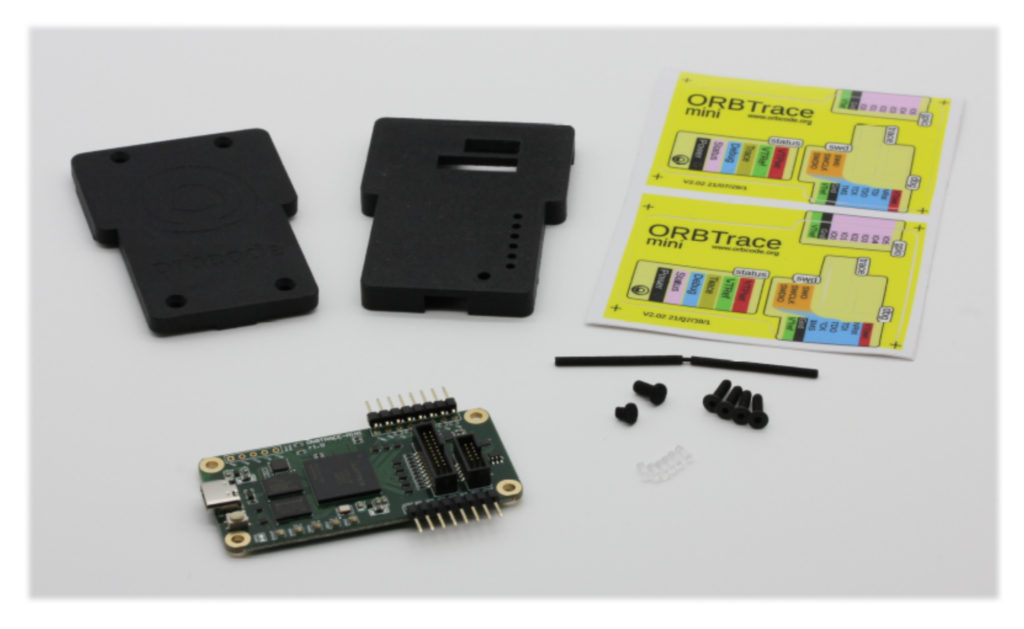
0.2 Check your components. You should have;
- ORBTrace mini PCB
- One LED guiding bar approximately 60mm long
- One long pushbutton head
- One short pushbutton head
- Case bottom
- Case top
- 4 x M2.5x10mm hex head countersunk screws
- 1.5mm Hex wrench (Not pictured)
- 6 transparent light pipes
- Vinyl top surface transfer printed on one side, sticky on the other
0.3 You should have already soldered the horizontal breakout pins to your ORBTrace mini board.
1. Vinyl fixing
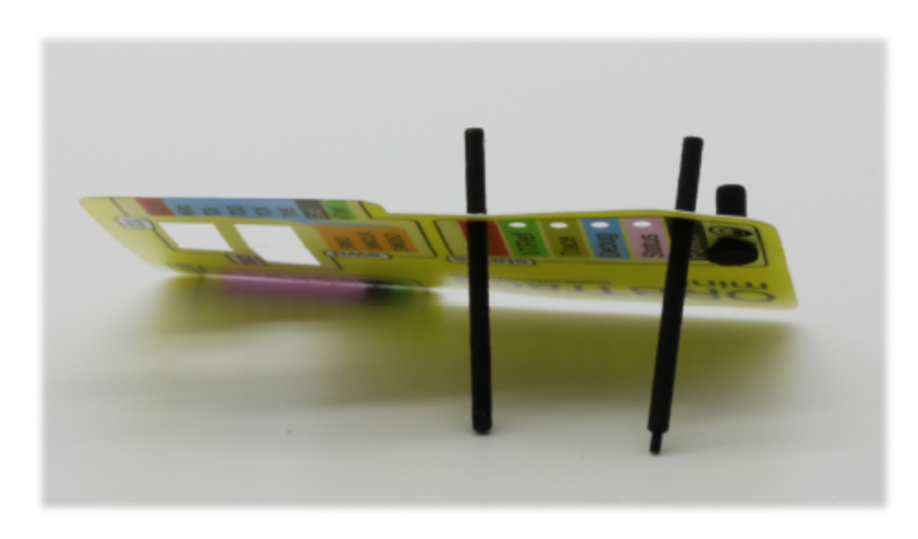
1.1 Snap the LED guiding bar in the middle into two pieces of equal length.
1.2 Remove the vinyl from its backing.
1.3 Push one piece of LED guiding bar through the top, VTPwr, hole in the vinyl so that approximately 10mm protrudes on the sticky side.
1.4 Do the same with the other piece of LED guiding bar through the bottom, Power, hole.
1.5 Push the long pushbutton head through the vinyl from the printed side, so it protrudes on the sticky side. At this point you should have three protrusions on the sticky side of the vinyl…we’ll use those to register it into the correct place on the case top.
1.6 Offer the vinyl to the case top. The LED guiding bars go through the top and bottom LED holes, and the pushbutton protrusion goes into the pushbutton hole.
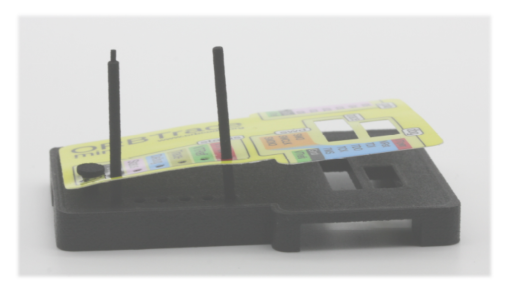
1.7 Push the vinyl into place by sliding the guiding plastics further into the holes, then smooth the rest of the vinyl onto the case top, watching out for kinks and creases. The adhesive is re-positionable (a limited number of times!), so just peel it up and go again if it doesn’t quite go down right the first time.
1.8 Remove the guiding plastics and smooth the vinyl into place. Pay particular attention to the edges as you don’t want dirt getting under those.
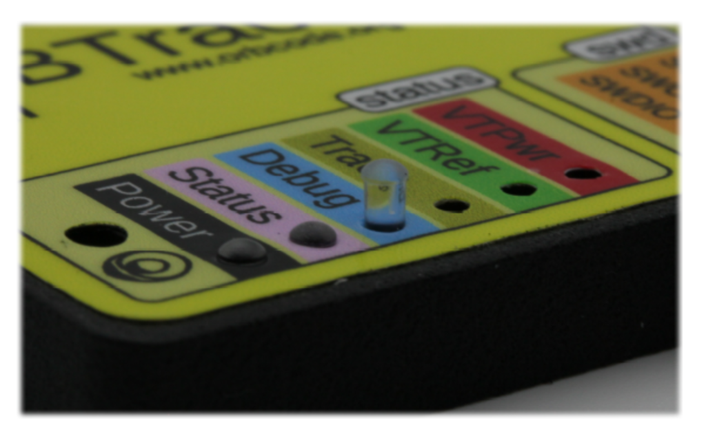
2. Fitting the lightpipes
2.1 Find a clean area. We’re not kidding, you will drop at least one of these, and they’re transparent, so you need as many factors as possible on your side if you ever want to see them again.
2.2 You can gently sand the bottom (non-rounded) end of the lightpipes for extra diffused lighting goodness. This step is not mandatory.
2.3 Offer up the lightpipe to the top (printed) side of the case. Wiggle it and push it gently through into position. No adhesive is needed. If it’s loose then remove it and squeeze it gently on the sides with pliers to deform it slightly…this is not normally needed.
2.4 Repeat for the other 5 lightpipes.
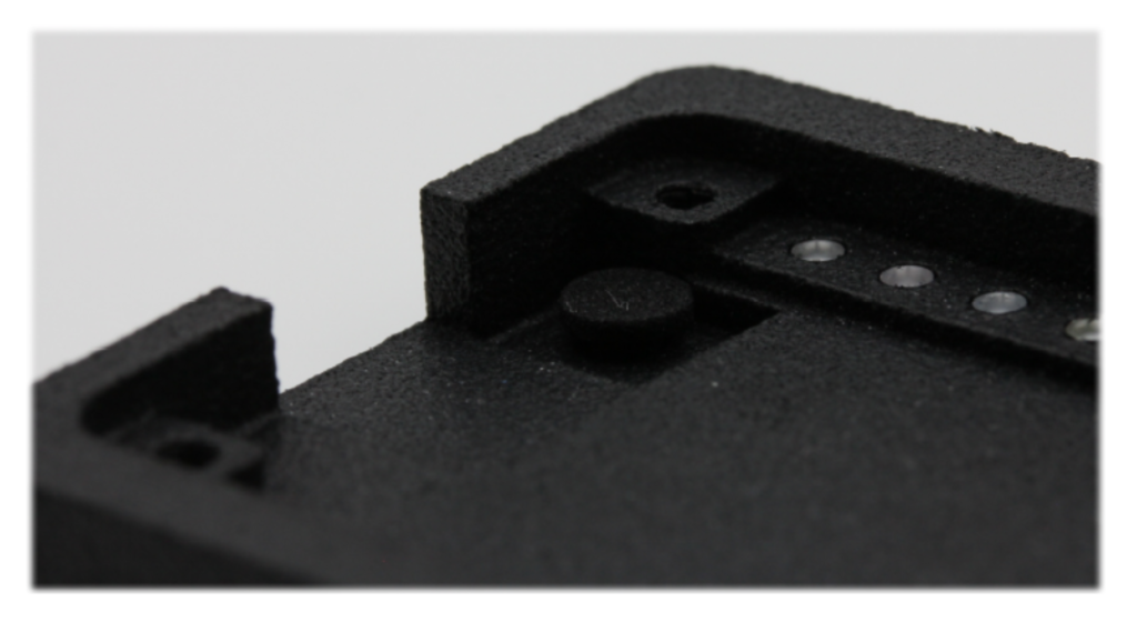
3 Case assembly
3.1 Put the short button into the button hole in the case from the inside so it protrudes outside through the vinyl
3.2 Place the PCB, FPGA-side to the case, into the case top.
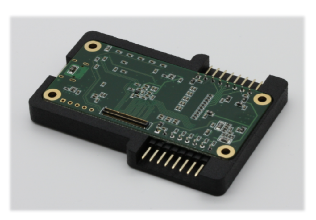
3.3 Offer up the case bottom and make sure it is well seated.
3.4 Put one of the screws through its hole. Apply gentle pressure to start it to bite into the plastic and loosely tighten the screw. While tightening don’t be tempted to go too fast when it’s cutting it’s thread … that will generate a lot of heat that can cause the thread to deform or strip.
3.5 Repeat for the diagonally opposite screw and then the other two screws as well.
3.6 finish tightening the screws in diagonal sequence. Be careful not to over-tighten as this can strip the screw thread.
3.7 Stick the remaining vinyls on your laptop, forehead or other location where you can advertise the fact you’re an ORBist.